
In-Depth Guide to Metric Thread Parameters: From Fundamentals to Practical Applications
Metric threads (e.g., M6, M10) are among the most widely used thread standards in machining. For manufacturers and users of metal cutting tools, understanding these parameters is not only fundamental to tool design but also critical to ensuring machining quality. This article presents a comprehensive yet accessible explanation of core metric thread parameters, highlighting practical considerations and common production issues.

1. Core Parameters of Metric Threads
1.1 Major Diameter
- Per ISO 228Plain explanation: The largest diameter of the thread, commonly referred to as the "outer diameter." For example, an M8 thread has a major diameter of 8 mm.
- Practical application:
- For external threads (e.g., bolts), the major diameter determines fit during assembly. If oversized, the thread may not engage; if undersized, it may be loose.
- When designing taps, the cutting portion must match the major diameter to ensure complete thread crests (see Figure 1).
1.2 Minor Diameter
- Per ISO 228Plain explanation: The smallest diameter of the thread, i.e., the root diameter.
- Practical application:
- An excessively large minor diameter reduces thread strength; too small, and internal threads (e.g., nuts) may not accommodate mating threads.
- Simplified formula:
- Minor Diameter ≈ Major Diameter − 1.1 × Pitch (e.g., for M10×1.5: 10 − 1.1×1.5 ≈ 8.35 mm)
1.3 Pitch Diameter
- Per ISO 228Plain explanation: The "mid-diameter" of the thread, which governs the tightness or looseness of thread fit.
- Practical application:
- Pitch diameter is the key parameter checked using thread gauges in quality inspection.
- Deviations can cause difficult engagement or looseness in assembled parts.

1.4 Pitch
- Per ISO 228Plain explanation: The axial distance between corresponding points on adjacent thread crests (see Figure 2).
- Classification and application:
- Coarse pitch (e.g., M12×1.75): Used for general fastening; allows fast installation and has high tensile strength.
- Fine pitch (e.g., M12×1.25): Preferred in precision applications and provides better resistance to loosening.
1.5 Thread Angle (60° Standard Angle)
- Per ISO 228Plain explanation: The included angle between the flanks of the thread; standardized at 60° for metric threads.
- Common mistake:
- Tool wear or misalignment can cause angular deviations, leading to poor thread engagement (e.g., wrench slipping issues).
2. Advanced Concepts: Tolerance and Engineering Calculations
2.1 Major Diameter Tolerance and Fit Failure
- Per ISO 228ISO 724 standard: Major diameter tolerances for metric threads are specified as 6g for external threads and 6H for internal threads. For instance, M12×1.75 external threads must fall within 11.908–11.682 mm.
- Failure case: An exported M20 bolt had a measured major diameter of 19.95 mm (lower limit: 19.92 mm), causing seizure during assembly.
- Root cause: uncorrected tool wear.
2.2 Pitch Diameter Calculation and Compensation
- Per ISO 228Theoretical formula: Pitch Diameter = Major Diameter − 0.6495 × Pitch
- Practical consideration: Actual Pitch Diameter = Theoretical Pitch Diameter + Δ (Δ = 0.02 to 0.05 mm depending on material hardness)
- CNC programming adjustment: In G76 threading cycles, pitch diameter can be fine-tuned using the Q value (finishing allowance) and R value (taper compensation).
2.3 Limit Design of Thread Pitch
- Fine pitch limit: According to DIN 13, the minimum pitch for threads below M36 is 0.35 mm (e.g., M4×0.35), requiring single-point thread milling at ≤15 m/min.
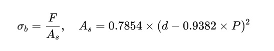
- Strength check for coarse threads:
- Tensile strength formula:
-
Where d is major diameter, P is pitch, and A_s is stress cross-sectional area.
3. How Do These Parameters Affect Machining Quality?
3.1 Balance Between Major and Minor Diameters
- Issue: When turning external threads to the exact nominal major diameter (e.g., M10 to 10 mm), crest sharpness may cause chipping or breakage.
- Solution: Leave a 0.05 mm allowance during roughing, and reach final dimensions in finishing passes.
3.2 Relationship Between Pitch and Tool Life
- Observation: Fine-pitch threads (e.g., M6×0.5) often result in broken taps.
- Cause: Smaller pitch leads to more concentrated cutting forces.
- Improvement: Use cobalt-alloyed high-speed steel taps (HSS-E), and reduce spindle speed (recommended <200 rpm).
3.3 Hidden Impact of Thread Angle
- Case study: A customer reported loose threads produced with a carbide end mill. Inspection showed the flank angle was 58° instead of 60°, reducing the contact area.
- Improvement: Use a profile projector to regularly inspect tool angles. Rework if deviation exceeds ±0.5°.
4. Frequently Asked Questions in Production
Q1: Thread gauge passes, but assembly is tight or stuck?
- Cause: Burrs at the crest or poor surface roughness (Ra > 3.2 µm).
- Solution: Apply cutting fluid during finishing or use taps with polished flutes.
Q2: Chips accumulate at the bottom of blind holes?
- Cause: Incompatible chip flute design.
- Solution: Use spiral-fluted taps (chip evacuation upwards) for blind holes; straight-fluted taps for through holes.
Q3: Why does the same tap wear out faster in stainless steel than in carbon steel?
- Cause: Stainless steel causes more galling and requires specialized coatings (e.g., TiAlN).
- Recommendation: Categorize taps by material type to avoid mixed use.
5. Purchasing Recommendations
5.1 Key Parameters When Ordering Taps
- Thread specification (e.g., M8×1.25)
- Workpiece material (e.g., 304 stainless steel)
- Hole type (through-hole or blind hole)
5.2 Relationship Between Drill Size and Thread
- Pre-drilling is required before tapping.
- Formula:
- Drill Diameter ≈ Major Diameter − Pitch
- Example: M10×1.5 → Drill Diameter ≈ 10 − 1.5 = 8.5 mm
6. Conclusion
Accurate control of metric thread parameters is fundamental to ensuring product quality. Ultimately, thread design is a balance of mechanical performance, machining efficiency, and economic viability. From the impact of major diameter tolerances on assembly, to how coatings affect tool longevity, every detail must be dynamically adjusted based on material and process conditions. In a globalized manufacturing landscape, companies must master differences between ISO, DIN, and ASME standards, while also embracing cutting-edge technologies like intelligent monitoring and nano-coatings. This article provides a multi-dimensional knowledge framework—from theory to practice—aimed at helping professionals fortify quality control and tackle market complexities through high-efficiency production.
OEM Capability
 We like to do design according to all the customers' requirements, or offer them our new designs. With strong OEM/ODM capabilities, we can fill your sourcing demands.
 Categories
| HSS-PM Taps | HSSE-M42 Taps |
| HSSE / HSS Taps | Spiral Flute Taps |
| Straight Flute Taps | Spiral Point Taps |
| Multi-function Taps |
| Solid Carbide Drill Bits | Twist Drill Bits |
| Center Drill Bits | Indexable U Drills |
| Flat-end Milling Cutter | Ball Nose End Mills |