
1. Importance and Application Fields of Milling Tools
Milling tools, as one of the core cutting tools in manufacturing, are widely used in industries such as aerospace, automotive, mold manufacturing, electronics, and general machinery. They enable efficient cutting processes, including face milling, slot milling, profile cutting, and complex surface machining. The proper selection of milling tool geometry not only improves processing efficiency but also significantly enhances workpiece surface quality, extends tool life, and reduces production costs.
2. The Key Role of Geometry Parameters in Tool Design and Performance
The geometry parameters of milling tools, mainly helix angle, number of cutting edges, and flute geometry, directly determine critical performance indicators such as chip formation, chip removal ability, cutting forces, and heat generation during machining. A proper geometric design effectively balances tool strength and cutting performance, improving machining stability and quality.
3. Basic Knowledge and Overview of Milling Tools
3.1 Definition and Classification of Milling Tools
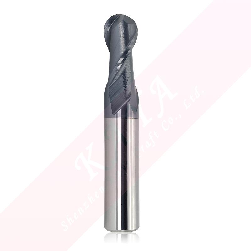
Milling tools are rotary cutting tools with multiple cutting edges, designed for use on milling machines or machining centers to process various materials. Depending on their application and structure, milling tools can be classified as end mills, face mills, ball end mills, keyway cutters, and slab mills.
3.2 Main Components of Milling Tools
Tool Materials: Common materials include high-speed steel (HSS), carbide, ceramics, and cubic boron nitride (CBN). The material selection depends on the workpiece material and cutting conditions.
Cutting Edges: The sharpness of the cutting edge directly affects cutting force and surface quality.
Coatings: Coatings such as TiAlN, TiCN, etc., improve the wear resistance and thermal stability of the tool.
3.3 Basic Principles of Milling
Milling is a multi-edge cutting process where the rotating tool and the feeding movement of the workpiece combine to remove material. Each cutting edge intermittently engages the workpiece to create chips and remove them.
3.4 Basic Concepts of Milling Tool Geometry Parameters
The geometric parameters describe the shape and structure of the tool. These parameters, including helix angle, number of cutting edges, and flute geometry, directly impact the mechanical and thermal behavior during the cutting process.
4. Helix Angle
4.1 Definition and Role of Helix Angle
The helix angle is the angle formed between the flute of the tool and the axis of the tool. It affects the smoothness of the tool's entry into the material, chip removal direction, and machining stability.
4.2 Influence of Helix Angle on Tool Performance
Cutting Force Distribution: A larger helix angle helps distribute the cutting force, reducing vibrations and improving surface finish.
Chip Removal Ability: A higher helix angle aids in smoother chip removal, making it suitable for machining sticky materials.
Tool Strength and Rigidity: A lower helix angle provides higher tool strength, suitable for heavy-duty cutting.
4.3 Selection and Optimization of Helix Angle
Low Helix Angle (15°-25°): Suitable for hard materials and rough cutting, offering higher tool strength.
Medium Helix Angle (30°-40°): Suitable for general applications, balancing chip removal and tool strength.
High Helix Angle (45° and above): Suitable for high-speed machining of materials like aluminum alloys and stainless steel, improving surface finish.
5. Number of Cutting Edges
5.1 Definition and Types of Cutting Edges
The number of cutting edges refers to the number of active cutting edges on the tool. Common types include single-edge, double-edge, and multi-edge milling tools.
5.2 Influence of Cutting Edge Number on Tool Performance
Single-edge and Double-edge Tools: These provide large chip space, suitable for soft materials, and result in lower cutting forces, ideal for high-speed cutting.
Multi-edge (3 or more): Increases feed rate and processing efficiency but requires careful consideration of chip removal space.
Cutting Stability: More cutting edges reduce tool vibration and improve surface quality.
5.3 Application Scenarios of Different Numbers of Cutting Edges
2-edge Tools: Suitable for machining aluminum and other soft materials.
3-edge Tools: Suitable for general-purpose applications, offering a balance between chip removal and rigidity.
4-edge and Multi-edge Tools: Suitable for hard materials and high-precision machining, improving processing efficiency.
6. Flute Geometry
6.1 Definition and Classification of Flute Geometry
Flute geometry refers to the shape of the grooves on the tool body designed to facilitate chip removal and coolant delivery. Common flute types include straight flutes, spiral flutes, and internal coolant flutes.
6.2 Influence of Flute Geometry on Cutting Performance
Straight Flute: Offers cutting stability, ideal for brittle materials.
Spiral Flute: Improves chip removal, suitable for ductile materials.
Internal Coolant Flute: Delivers coolant directly to the cutting zone, enhancing temperature control during machining.
6.3 Application and Selection of Different Flute Types
Straight Flute Tools: Commonly used for machining cast iron and brittle materials.
High Spiral Flute Tools: Suitable for non-ferrous metals and high-speed cutting.
Internal Coolant Flute Tools: Ideal for deep hole machining and difficult-to-machine materials.
7. Comprehensive Consideration of Helix Angle, Cutting Edges, and Flute Geometry
7.1 Coordination and Interdependence of Different Geometry Parameters
Helix Angle and Cutting Edges: High helix angles combined with fewer cutting edges enhance chip removal; low helix angles with more cutting edges are ideal for hard materials.
Cutting Edges and Flute Geometry: More cutting edges require optimized flute design to ensure proper chip removal.
Helix Angle and Flute Geometry: High helix angles are best paired with spiral flutes for optimal chip removal and cooling.
7.2 How to Balance Helix Angle, Cutting Edges, and Flute Geometry
Select the appropriate helix angle and cutting edges based on the material being processed.
Consider surface finish requirements and cutting speeds when selecting flute geometry.
Optimize geometry parameters based on the rigidity of the processing equipment and feed conditions.
For deep hole machining, prioritize internal coolant flutes and appropriate cutting edges to ensure smooth chip removal.
Through a thorough understanding and application of helix angle, cutting edges, and flute geometry, significant improvements can be made in milling efficiency, surface quality, tool life, and overall cost reduction. Proper selection and optimization of these parameters require a comprehensive consideration of processing conditions, material characteristics, and equipment capabilities to achieve optimal machining results.
OEM Capability
 We like to do design according to all the customers' requirements, or offer them our new designs. With strong OEM/ODM capabilities, we can fill your sourcing demands.
 Categories
| HSS-PM Taps | HSSE-M42 Taps |
| HSSE / HSS Taps | Spiral Flute Taps |
| Straight Flute Taps | Spiral Point Taps |
| Multi-function Taps |
| Solid Carbide Drill Bits | Twist Drill Bits |
| Center Drill Bits | Indexable U Drills |
| Flat-end Milling Cutter | Ball Nose End Mills |